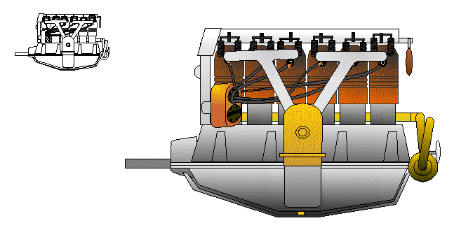
To those used to modern automobile engines, the liquid-cooled aero-engines of the First World War can seem rather bizarre. The Hispano-Suiza firm cast cylinder blocks for its famous V-8s, but most manufacturers built cylinders individually, by brazing copper- or steel-sheet water jackets around a forged cylinder. The non-detachable cylinder head was usually an integral part of the forging. Valve stems, springs, and rockers arms were almost always left exposed to the air in the hope that the slipstream would make up for the inadequate cooling systems and detonation-prone fuels of the time. To us, the results often look more like an engineering- museum cutaway than a complete, functioning powerplant.
This characteristic, built-up construction presents some problems for the modeler. The separate cylinders, water jackets, coolant passages, cam boxes, cam drives, exposed valve gear, and separate crankcase make the impression of bewildering complexity the main thing we have to represent, particularly when we throw in the normal ancillaries of the internal combustion engine: water pump, carburetor, inlet manifold, exhaust system, magnetos, and ignition wires. But, unfortunately, the one-piece lump of styrene, white-metal, or resin that comes in kits and detail sets does not look much like a multipart, multiple-material original. Representing these engines convincingly will, in all likelihood, always demand more pieces than the manufacturers will be prepared to supply. Nor can you count on hiding lack of detail with a cowling, either. Until high-octane fuel, sodium-filled valves, and glycol-water coolant mixtures came along, most engines ran too hot to tolerate a full cowling, even when one was provided.
I first recognized this dilemma while contemplating my sample of the infamous Glencoe Models Oeffag-Albatros D III. This aircraft had a very prominent, Austro-Daimler six-cylinder engine protruding through its large cowl opening. The kit engine was as accurate in outline as anything in the kit: i.e. too small and all but lacking in detail. The project seemed hopeless until I remembered the rack of K&S-brand metal tubing at the hobby shop. Here were pre-fabricated metal shapes that approximated the basic forms of the Austro-Daimler.
As always, I started looking for reference material on the Austro-Daimler. Engines are not as popular a subject as entire aircraft. But in a local university library, I found 1917, 1918, and 1920 editions of Jane's All the World's Aircraft, reprinted by the Johnson Reprint Company. The engine sections contain large photographs of the engines then in use, along with detailed technical reports and engineering drawings on some types (though not on the Austro-Daimler). Other references were obtained using the Inter-Library Loan service (consult the reference librarian at you public library).
Once I had photos to work from, I had to decide what I would include in my model. The bewildering array of objects on the Austro-Daimler had to be organized and made comprehensible to the viewer. Too much detail would clutter the engine, confusing the audience and diluting the effect I was looking for. Individually accurate pieces would look over-scale or out of place. But too few parts would cause the opposite problem, the all-in-one-piece look that I was trying to get away from. I therefore tried to reduce the engine to major functional groups that would strike viewers as wholes. I asked myself what parts would have been handled as sub-assemblies when the engines were built up and what parts would have formed complete sub-systems: electrical, fuel, etc. Then I took a quick, "snapshot" look at the photos and sketched the sub-assemblies, in their proper positions, from memory. This technique let me simplify without losing important, meaningful information. It helped identify the parts that really mattered: the features that struck the knowledgeable viewer first. I found that I'd need a crankcase and sump, a cam box, cylinders, exhaust pipes, inlet manifolds, a carburetor, magnetos, water pump, oil and coolant lines, and valve springs.
It is a good idea to think about materials, colors, and textures at this stage. Variations in tone and surface create much of the visual complexity of full-scale engines. No single material—i.e. paint—can adequately represent the subtly variegated appearance of unpainted machinery. Paint can reproduce a shade fairly well and can do a good job depicting rough castings. But it seldom catches the play of light on bare metal, particularly smooth extrusions and parts machined from dissimilar alloys. By using a range of materials, including several different metals, I was able to capture this kind of variation nicely. Jane's sometimes mentions the materials used for different components. But, even when it does not, black and white photos can give you much information. Look for variations in tone and texture on the photo. The Austro-Daimler had copper-sheet water jackets, forged steel cylinder barrels, and aluminum inlet manifolds, cam box, and crankcase. Tonal differences were perfectly visible, even in the reproduction, black-and-white pictures.
When I knew what effects I had to try for, I could decide how I was going to proceed. I used grainy, metallic paint to simulate rough-surfaced metal, like castings and welds, and real metal for smooth-finished parts. The textural contrast between the painted and the bare-metal parts would, I hoped, heighten the metallic effect of the paint, because, in such cases, the eye sees a difference in fabrication methods rather than a difference in material. Copper tubing was the obvious choice for the water jackets. The carburetor, water pipes, and coolant pump would be brass. Passing the copper parts through a flame would reduce the bright metal to a more realistic, dull brown. I would do the same with aluminum tube to model steel forgings, like cylinder barrels. I would build the crankcase from laminated styrene roughed up with liquid cement (to represent the cast surface). Here a grainy aluminum paint would look perfectly realistic. Handling the delicate metallized paint would gives it the grimy appearance that typified engines with lots of joints and poor gasket technology.

Finally, with the research and documentation complete, I was ready to create the scale drawings for the model engine. These contained only the minimum information needed for checking the sizes and locations of parts—I put in no extraneous details that would complicate life later. I had a reference that gave the length and height of the Austro-Daimler as 172 and 115 cm, respectively. But, unfortunately, older, non-modeling references often fail to list overall dimensions. You usually have to deduce the measurements from the cylinder bore and stroke. Using these figures, you can estimate the external dimensions pretty accurately. First, figure out the size of a finished cylinder by adding an allowance for the water jacket, cylinder walls, and cylinder spacing to the bore diameter. Use a set of dividers to walk off the length of all the cylinders in a bank. Then use the cylinder to scale other objects in the reference photographs. Using the Austro-Daimler's 13.5 cm bore and 17.5 cm stroke, I estimated the engine's length to within a couple of scale inches of published figures. I used pencil and paper for my first set of plans and reduced them on a photocopy machine. But, of course, a computer makes things much easier.
It is best to build the engine from the bottom up. I built the crankcase and sump from laminated styrene sheet, because it was familiar and would do the job. But you could just as easily cast the, in white metal or resin or sculpt them from Sculpey modeling compound. I cemented a flange made from .010" styrene to the bottom of the crankcase and a thicker styrene reinforcing plate to the underside of the sump. Smaller details were made from styrene and superglue.
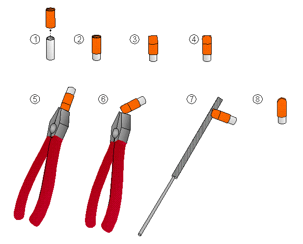
When the bottom end of the engine was done, I started in on the cylinder barrels and their jackets. I cut the barrels from 3/32" aluminum tube and pressed them into 1/8" copper tube water jackets. I made the barrels a bit long to allow for the heads and to provide a good anchor in the crankcase. All parts were attached with super glue. To represent the pear-shaped cylinder heads, I pinched the top of each cylinder closed with a pliers. Then I rounded off the corners with a die-maker's file (also known as a rat-tail or Swiss file).
Next I drilled six, vertical, evenly spaced, 1/8" holes through the styrene crankcase. Since I did not have a drill press, I of course got one hole out of true. So I reamed it out with a rat-tail file until the cylinder would line up properly, filled the gap with a little baking soda, and added superglue. Then I superglued the remaining cylinders to the crankcase, checking that each cylinder was square to the block and in line with its neighbors. When the glue cured, I painted the crankcase aluminum and set it aside.
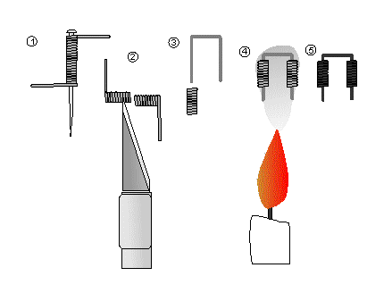
Tiny as they are in 1/48 scale, valve springs are responsible for much of the impression of complexity these engines produce. Happily, the springs proved easy to make. I made mine from fine wire pulled from a scrap of window screen. I wrapped the wire around a straight pin to form one long spring. Then I cut off the individual valve springs with a hobby knife. For the Austro-Daimler, I fitted each pair of springs to a U-shaped piece of the same wire and superglued it in place using the smallest possible amount of adhesive. This simulates the valve stems and fore-and-aft rocker arms of the original. The Austro-Daimler had four valves per cylinder, so I needed twelve pairs in all.
I was now ready to attach the springs. First, I filed and sanded away irregularities on the heads, until I had a perfectly even, pent-roof shape on all cylinders. For the final smoothing operation, I clamped wet-or-dry sandpaper to a glass sheet and rubbed the heads of the complete cylinder/crankcase assembly across it Next, I drew a layout line across the heads of all the cylinders using a soft pencil and a steel straight edge. using the line as a guide, I drilled mounting holes for the valve stems with a pin vise and a #78 bit. I superglued the valve-spring assemblies to the heads.
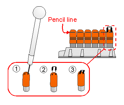
Using the same basic procedure, I attached brass-wire "spark plugs" and mounting pins for the exhaust and inlet pipes to each cylinder. A dab of typewriter correction fluid (or thick, white paint) on each spark plug does a nice job of representing the ceramic insulator. I put one plug on each side of each cylinder (the Austro-Daimler had dual ignition systems, with two plugs per cylinder and two magnetos). Then I quickly passed the cylinders through the flame of a wooden kitchen match. This darkens and dulls the metal and deposits soot on the head. The soot simulates the oil and grime that was unavoidable in the age of exposed valve trains and large production tolerances. But be careful! Superglue burns furiously if you overdo it. When the metal is cool, spray it with a semi-gloss clear coat to protect the delicate, oxidized finish from subsequent handling.
I made the two, three-branch intake manifolds from pieces of 1/16" aluminum tubing. I formed the curved sections by bending the tubing gently with a large-diameter dowel. This helped to keep the tube from collapsing in the corners. When the bends were right, I trimmed the ends to size. I carefully fitted the T-shaped butt joints between the center branch and the two side branches and between the branches and the trunk. I drilled holes for mounting pins in the cross pieces and radiused the ends of the tubes that would butt up against them using a round die-maker's file. Then I pinned the parts together with bits of fine brass wire and superglued them. I touched up the joints with aluminum paint. Remember that the more closely you fit the joint, the stronger the bond and the less paint you need to use. Superglue is strongest in thin layers over broad contact areas.
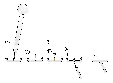
I made the carburetor by squeezing a piece of 1/8" brass tubing down to an oval cross section. I pinched the top closed and snipped off the corners. I glued on some detail made from bits of brass and fitted a brass mounting pin to each of the snipped corners. Then I fitted the valve sides of the inlet manifolds to the mounting pins on the heads. This let me locate the carburetor in relation to the two main manifold trunks. After some fine filing, when everything fit just right, I superglued the manifolds to the carburetor (NOT to the cylinder heads). This makes a solidly aligned assembly that should fit the heads perfectly when we stick everything together later.
I fashioned exhaust pipes from 1/16" aluminum tube. I thinned down the open end of each pipe from the inside, using a hand-turned drill bit and a round die-maker's file. I mount each pipe on a round toothpick. Then I painted them a rust color, using slow-drying enamel. When the pipes are almost but not quite dry, I rolled them in a mixture of finely powdered graphite and charcoal and sprayed them with clear coat. The slight cracking and blistering that resulted helped reproduce the corroded effect. I set them aside.
For the cam box, I slipped a piece of 1/8" aluminum tubing inside a length of 3/32" tube. I bevelled the front of the tubes with a flat file. Using a razor saw or knife, I cut a kerf in the bottom, parallel with the bevel, about 1/8" from the front of the tube, and about 1/3 of the diameter deep. This represents the prominent gear housing at the angle between the cam-drive shaft (the vertical tube at the front of the crankcase) and the cam box. Starting at the rear of the kerf, I filed the underside of the tube until I could bend the sides into a shallow oval section split by a narrow slot. I superglued a piece of 1/16" aluminum tubing into the slot, squeezed the free end of the 1/16" tube closed, and rounded it off with a die-maker's file. I mashed a slice of aluminum tubing into a disk and superglued it to the front of the gear case at the front of the cam box.
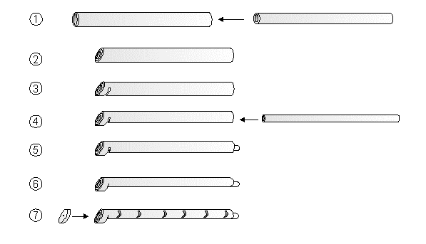
With the razor saw, I cut vertical slots in the sides of the cam box at the points shown on the plans. Then I superglued short pieces of wire into the slots to represent the Austro-Daimler's transverse rocker arms. I used piano wire because the dark steel contrasted well with the bright aluminum of the cam box.
To make the prominent fitting at the top rear of the cam box, I used brass tube and wire. I make a decompression lever with steel wire and a drop of super glue and painted the superglue a wood color. This lever let mechanics shift the rotation axis of the cams so that the exhaust valves would remain cracked open throughout the cycle. The resulting, lower the compression ratio made starting much easier—a major advantage when all starting was done by swinging the propeller round by hand.
I assembled a cam drive from pieces of 1/16" aluminum tube (a long one for the drive tube, two short ones for magneto drives, and a short one for the fitting on the front). I attached the parts with brass-wire pins and superglue. The magnetos were mounted one on each side, near the bottom of the cam-drive tube, at 45° to the engine center line when viewed from the top. Then I glued the cam drive to the cam box and set the completed cam-box assembly aside.
The magnetos were made from slightly flattened 3/32" or 1/8" copper tubing. I made the caps by supergluing two short pieces of solid, insulated wire, painted black, inside each copper housing. I then added details cut from brass wire and painted black. I set the magnetos aside.
Building the Cooling System
The Austro-Daimler's cooling system was the most complex and delicate part of the whole project, mainly because prominent water pumps at the rear of the engine. You wouldn't have to build this in most cases, of course, because it is usually out of sight. But having come this far, I wasn't going to leave anything out for so uncompelling a reason.
Like others of its kind, the Austro-Daimler had external water passages—brass pipes attached to the outside of the engine—rather than the invisible, cast-in-place passages of a modern Buick. One pipe ran along under the cam box to the top of each water jacket. It cannot be seen clearly. The other went along the starboard side of the engine. I omitted the former. The latter was made from 1/32" brass wire. I simulated the water-tight rubber connectors at each cylinder with strips of electrical tape and loops of the fine wire.
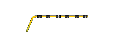
I made a water pump from various bits of tubing and wire. I didn't have a clear illustration, so I had to guess, using what photos I had and other, similar engines as a guide. Many of the parts were made by crushing short lengths of brass or aluminum tubing into donuts or wafers. I carefully pinned and superglued the parts together. I made the pump's inlet pipe from 1/16" brass tube and faired it into the starboard side of the pump, using files and a minimum of superglue. I fashioned the outlet to the radiator from a piece of 3/32" wire with a slice of 1/16" tube for the coupling. I attached the pump to the rear of the crankcase. Then I glued the rear of the starboard-side water passage to the the pump inlet and the front to the first cylinder. On the Albatros, one of the tubes from the over wing radiator connected to the pump outlet and the other connected to the 1/16" tube in the bottom of the cam box at the number one cylinder.
Now it was time to finish the model. I pinned and glued the cam box assembly to the cylinder heads and the crankcase. I attached the magnetos to the stubs on the cam-box drive. I cut pieces of fine cotton thread for the spark plug wires and superglued them to the terminals on the magnetos and to the ends of the spark plugs (remember to check the firing order for your engine and the way that wires were bundled). Then I glued the inlet manifold assembly and the exhaust pipes to their locating pins. I made a heating line from fine brass wire and attached it to the back of the carburetor and to the water pump. Finally, I cemented the sump to the crankcase and added the last few details. Like many First-War, the Austro-Daimler breathed through an updraft carburetor mounted on a duct in side of the sump. Incoming air passed though a tube in the warm sump (I think it opened at the front of the block, but I cannot be sure) and thence to the carb. This prevented carburetor icing. I made the duct from sheet styrene and cemented it in place under the carburetor. I used a thin line of superglue to tie the brass of the carb into the plastic duct. This makes the inlet assembly a bit more rigid. Finally, I painted the sump aluminum, dusted the assembled engine with finely ground graphite and charcoal, and sealed the whole with a coat of clear gloss.
I have now made four of these little motors (three Austro-Daimlers and an Isotta-Fraschini V4B). They take time, but they are neither difficult nor expensive to make. Even the tedious work is far more absorbing than the endless sanding and panel scribing most of us take for granted. The results are extremely rewarding. I'm often asked if my engines run, and even the Glencoe looked terrific with one installed. Most importantly of all, this kind of modeling has helped me to develop a deeper technical appreciation for the airplanes we model and for the airmen that flew and maintained them. To scratch-build one of these powerplants is as near as any of us are likely come to building an engine the way they did back then. It can help us to appreciate the risks they took and the compromises they lived with. As I did my first fit checks in the Albatros, I glimpsed the full implications of the airplane's lack of a firewall. All those joints I'd made, hand-fitted with file and sandpaper like the originals, now leaking coolant, fuel, and oil onto oil-soaked plywood and cloth-insulated electrical wires, practically at the pilot's feet. A cockpit full of gun gas and carbon monoxide. And people shooting at him while he flew the passes of Alps or skimmed the fog-shrouded fields of Flanders.
Text © 1997 by Robert Craig Johnson.